Privacy statement: Your privacy is very important to Us. Our company promises not to disclose your personal information to any external company with out your explicit permission.
หมายเลขรุ่น: NSO4GU3AB
การเดินทาง: Ocean,Air,Express,Land
ชนิดการชำระเงิน: L/C,T/T,D/A
Incoterm: FOB,EXW,CIF
4GB 1600MHz 240 พิน DDR3 UDIMM
ประวัติการแก้ไข
|
Revision No. |
History |
Draft Date |
Remark |
|
1.0 |
Initial Release |
Apr. 2022 |
|
![]()
ตารางข้อมูลการสั่งซื้อ
|
Model |
Density |
Speed |
Organization |
Component Composition |
|
NS04GU3AB |
4GB |
1600MHz |
512Mx64bit |
DDR3 256Mx8 *16 |
คำอธิบาย
Hengstar Unbuffered DDR3 SDRAM DIMMS (โมดูลข้อมูลสองเท่าที่ไม่ได้รับการบัฟเฟอร์แบบซิงโครนัส DRAM โมดูลหน่วยความจำแบบอินไลน์คู่) มีพลังงานต่ำโมดูลหน่วยความจำการทำงานความเร็วสูงที่ใช้อุปกรณ์ DDR3 SDRAM NS04GU3AB เป็น 512M x 64- บิตสองอันดับ 4GB DDR3-1600 CL11 1.5V SDRAM ผลิตภัณฑ์ DIMM ที่ไม่ได้รับการบัฟเฟอร์ซึ่งใช้ส่วนประกอบ FBGA 256M 256M x 8-bit SPD ถูกตั้งโปรแกรมให้กับเวลาแฝงมาตรฐาน DDR3-1600 ของ JEDEC ที่ 11-11-11 ที่ 1.5V DIMM 240 พินแต่ละอันใช้นิ้วสัมผัสทองคำ SDRAM Unbuffered DIMM มีไว้สำหรับใช้เป็นหน่วยความจำหลักเมื่อติดตั้งในระบบเช่นพีซีและเวิร์กสเตชัน
คุณสมบัติ
Power Supply: VDD = 1.5V (1.425V ถึง 1.575V)
VDDQ = 1.5V (1.425V ถึง 1.575V)
800MHz FCK สำหรับ 1600MB/วินาที/พิน
8ธนาคารภายในอิสระ
Latency CAS ที่ตั้งโปรแกรมได้: 11, 10, 9, 8, 7, 6
latency Additive Additive Latency: 0, Cl - 2 หรือ Cl - 1 นาฬิกา
8บิตล่วงหน้า
ความยาวเบิร์สต์: 8 (interleave โดยไม่มีขีด จำกัด ใด ๆ ตามลำดับที่อยู่ที่อยู่เริ่มต้น“ 000” เท่านั้น), 4 กับ TCCD = 4 ซึ่งไม่อนุญาตให้อ่านหรือเขียนได้อย่างไร้รอยต่อ [ไม่ว่าจะโดยใช้ A12 หรือ MRS]
data data data data data
การสอบเทียบ (ตนเอง) การสอบเทียบตนเองภายในผ่าน ZQ PIN (RZQ: 240 OHM ± 1%)
การเลิกตายโดยใช้ PIN ODT
ช่วงเวลาการรีเฟรชค่าเฉลี่ย 7.8US ที่ต่ำกว่า TCASE 85 ° C, 3.9US ที่ 85 ° C <TCASE <95 ° C
การรีเซ็ต asynchronous
ความแข็งแรงของไดรฟ์ข้อมูลที่ปรับได้ไม่ได้
topology
PCB: ความสูง 1.18” (30 มม.)
Rohs เป็นไปตามข้อกำหนดและปราศจากฮาโลเจน
พารามิเตอร์เวลาที่สำคัญ
|
MT/s |
tRCD(ns) |
tRP(ns) |
tRC(ns) |
CL-tRCD-tRP |
|
DDR3-1600 |
13.125 |
13.125 |
48.125 |
2011/11/11 |
ตารางที่อยู่
|
Configuration |
Refresh count |
Row address |
Device bank address |
Device configuration |
Column Address |
Module rank address |
|
4GB |
8K |
32K A[14:0] |
8 BA[2:0] |
2Gb (256 Meg x 8) |
1K A[9:0] |
2 S#[1:0] |
คำอธิบายพิน
|
Symbol |
Type |
Description |
|
Ax |
Input |
Address inputs: Provide the row address for ACTIVE commands, and the column |
|
BAx |
Input |
Bank address inputs: Define the device bank to which an ACTIVE, READ, WRITE, or |
|
CKx, |
Input |
Clock: Differential clock inputs. All control, command, and address input signals are |
|
CKEx |
Input |
Clock enable: Enables (registered HIGH) and disables (registered LOW) internal circuitry |
|
DMx |
Input |
Data mask (x8 devices only): DM is an input mask signal for write data. Input data is |
|
ODTx |
Input |
On-die termination: Enables (registered HIGH) and disables (registered LOW) |
|
Par_In |
Input |
Parity input: Parity bit for Ax, RAS#, CAS#, and WE#. |
|
RAS#, |
Input |
Command inputs: RAS#, CAS#, and WE# (along with S#) define the command being |
|
RESET# |
Input |
Reset: RESET# is an active LOW asychronous input that is connected to each DRAM and |
|
Sx# |
Input |
Chip select: Enables (registered LOW) and disables (registered HIGH) the command |
|
SAx |
Input |
Serial address inputs: Used to configure the temperature sensor/SPD EEPROM address |
|
SCL |
Input |
Serial |
|
CBx |
I/O |
Check bits: Used for system error detection and correction. |
|
DQx |
I/O |
Data input/output: Bidirectional data bus. |
|
DQSx, |
I/O |
Data strobe: Differential data strobes. Output with read data; edge-aligned with read data; |
|
SDA |
I/O |
Serial |
|
TDQSx, |
Output |
Redundant data strobe (x8 devices only): TDQS is enabled/disabled via the LOAD |
|
Err_Out# |
Output (open |
Parity error output: Parity error found on the command and address bus. |
|
EVENT# |
Output (open |
Temperature event: The EVENT# pin is asserted by the temperature sensor when critical |
|
VDD |
Supply |
Power supply: 1.35V (1.283–1.45V) backward-compatible to 1.5V (1.425–1.575V). The |
|
VDDSPD |
Supply |
Temperature sensor/SPD EEPROM power supply: 3.0–3.6V. |
|
VREFCA |
Supply |
Reference voltage: Control, command, and address VDD/2. |
|
VREFDQ |
Supply |
Reference voltage: DQ, DM VDD/2. |
|
VSS |
Supply |
Ground. |
|
VTT |
Supply |
Termination voltage: Used for control, command, and address VDD/2. |
|
NC |
– |
No connect: These pins are not connected on the module. |
|
NF |
– |
No function: These pins are connected within the module, but provide no functionality. |
หมายเหตุ : ตารางคำอธิบายพินด้านล่างเป็นรายการที่ครอบคลุมของพินที่เป็นไปได้ทั้งหมดสำหรับโมดูล DDR3 ทั้งหมด พินทั้งหมดที่ระบุไว้ในพฤษภาคม ไม่ได้รับการสนับสนุนในโมดูลนี้ ดูการกำหนด PIN สำหรับข้อมูลเฉพาะสำหรับโมดูลนี้
ไดอะแกรมบล็อกการทำงาน
4GB, 512MX64 โมดูล (2RANK ของ X8)


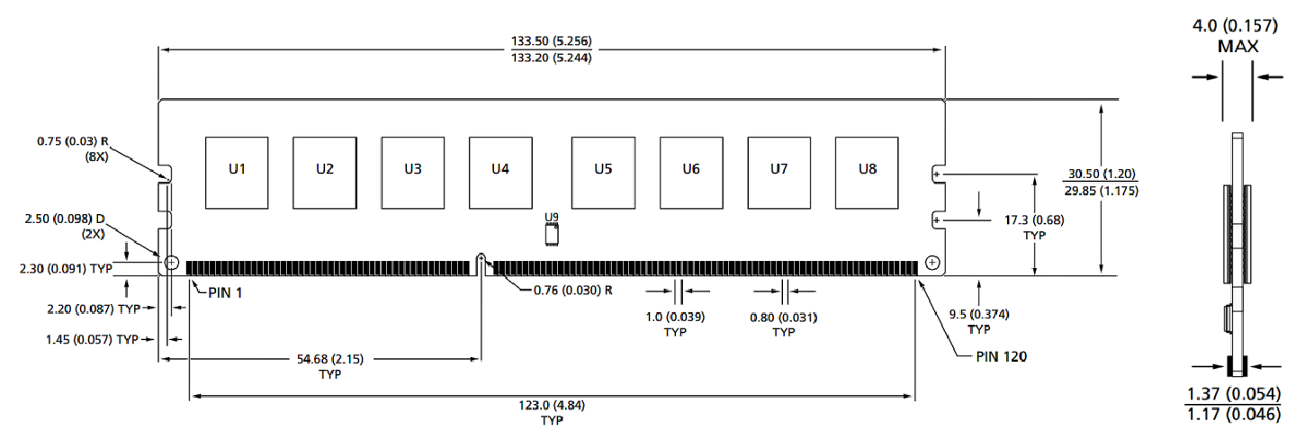
ขนาดของโมดูล
มุมมองด้านหน้า

มุมมองด้านหน้า

หมายเหตุ:
1. ขนาดทั้งหมดอยู่ในมิลลิเมตร (นิ้ว); สูงสุด/นาทีหรือทั่วไป (typ) ที่ระบุไว้
2. การยอมรับในทุกมิติ± 0.15 มม. เว้นแต่จะระบุไว้เป็นอย่างอื่น
3. ไดอะแกรมมิติสำหรับการอ้างอิงเท่านั้น
ประเภทผลิตภัณฑ์ : อุปกรณ์เสริมโมดูลสมาร์ทอุตสาหกรรม


Privacy statement: Your privacy is very important to Us. Our company promises not to disclose your personal information to any external company with out your explicit permission.

Fill in more information so that we can get in touch with you faster
Privacy statement: Your privacy is very important to Us. Our company promises not to disclose your personal information to any external company with out your explicit permission.